
Limit System Technical Guide
Tubular Motor Limit Switch
Mechanical and electronic upper and lower travel control for blinds, shutters, awnings and screens
A tubular motor limit switch controls where the motor stops. Correct selection and model-specific commissioning help prevent over-travel, incorrect curtain position and repeated mechanical stress.
Quick Answer
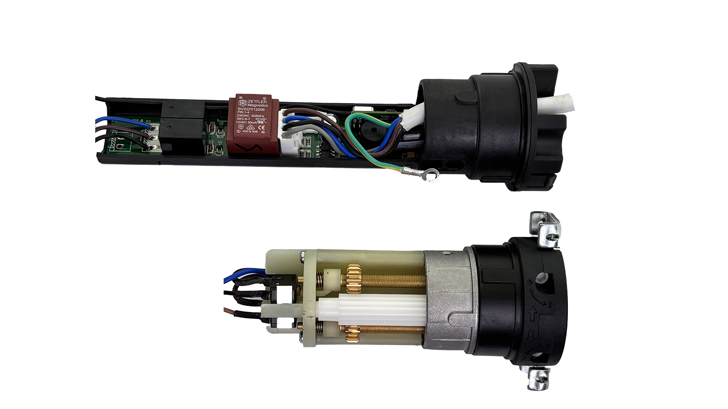
A tubular motor limit switch defines the upper and lower stop positions of a roller blind, roller shutter, awning, zip screen or projection screen. Mechanical systems normally use a geared counting mechanism and adjustable cams. Electronic systems save stop positions through electronic control logic and a model-specific feedback method. A remote control or programming tool may be used to set an electronic limit, but it is not a third type of limit system.
What Is a Tubular Motor Limit Switch?
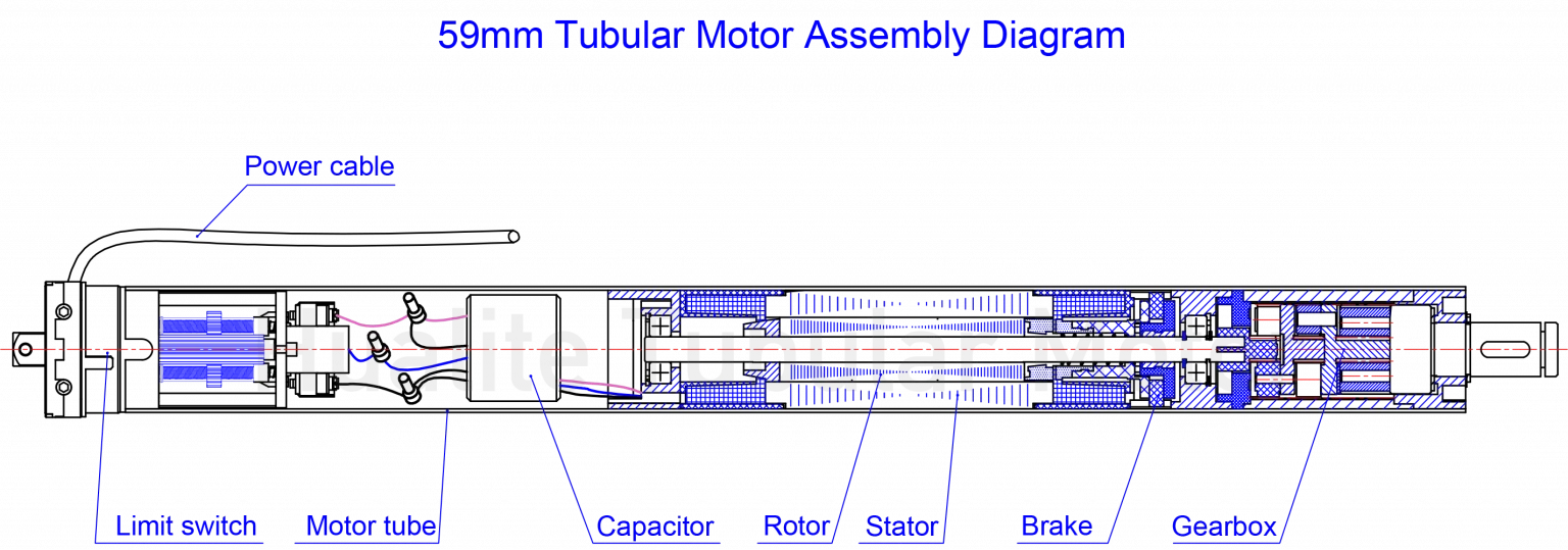
The limit system is the part of a tubular motor that determines when travel must stop in each direction. As the motor turns the roller tube, the system tracks travel and interrupts or changes the relevant control path when the preset upper or lower position is reached.
Correct limit control keeps a roller blind at the intended drop, prevents a shutter curtain from being driven beyond its end position, controls awning extension and retraction, and helps a zip screen or projection screen finish travel at the required point. The correct mechanism and setting procedure depend on the motor model, installation direction, control system and application.
Why Limit Control Matters
Controls usable travel
Upper and lower limits define the operating range instead of allowing the motor to continue indefinitely.
Protects the application
Correct stopping reduces the risk of over-winding fabric, forcing shutter components or over-tensioning an awning or screen.
Supports consistent commissioning
Installer checks can confirm that the motor, tube, crown, drive, brackets and controls work together at both end positions.
How Mechanical Limits Work
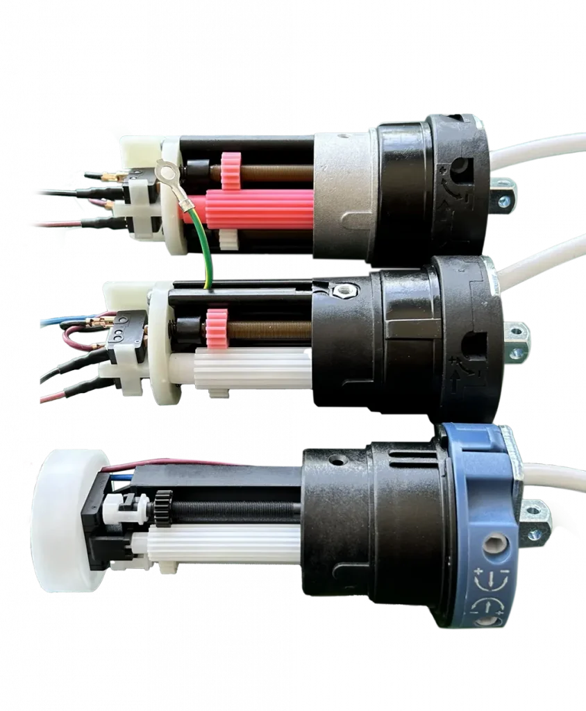
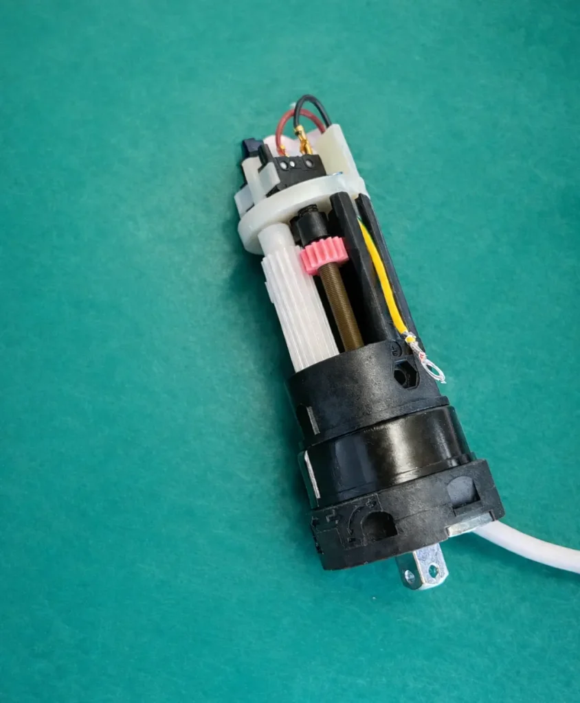
A mechanical tubular motor limit normally links tube or motor rotation to a reduction gear or counting mechanism. As the mechanism advances, separate adjustable cams correspond to the two travel directions. When the preset position is reached, the relevant cam operates a stop mechanism or opens the circuit for that direction.
Adjustment screws or a setting tool move the cam positions. The symbols, screw location and direction of adjustment vary by motor model, installation orientation and rotation direction. For that reason, there is no universal clockwise or counter-clockwise instruction that is safe for every tubular motor.
How Electronic Limits Work
An electronic limit system stores the required stop positions through electronic position records, control logic or the feedback method used by the specific motor. The controller then compares movement with the saved positions and stops the applicable direction at the programmed endpoint.
The feedback method and commissioning sequence are model-specific. Depending on the product, the installer may use a wall control, paired transmitter, receiver sequence or programming tool. These are setting and control interfaces; they do not create a separate “receiver-based” limit category alongside mechanical and electronic limits.
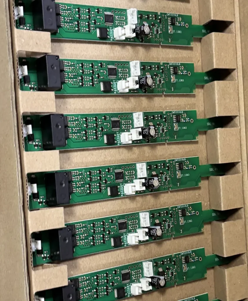
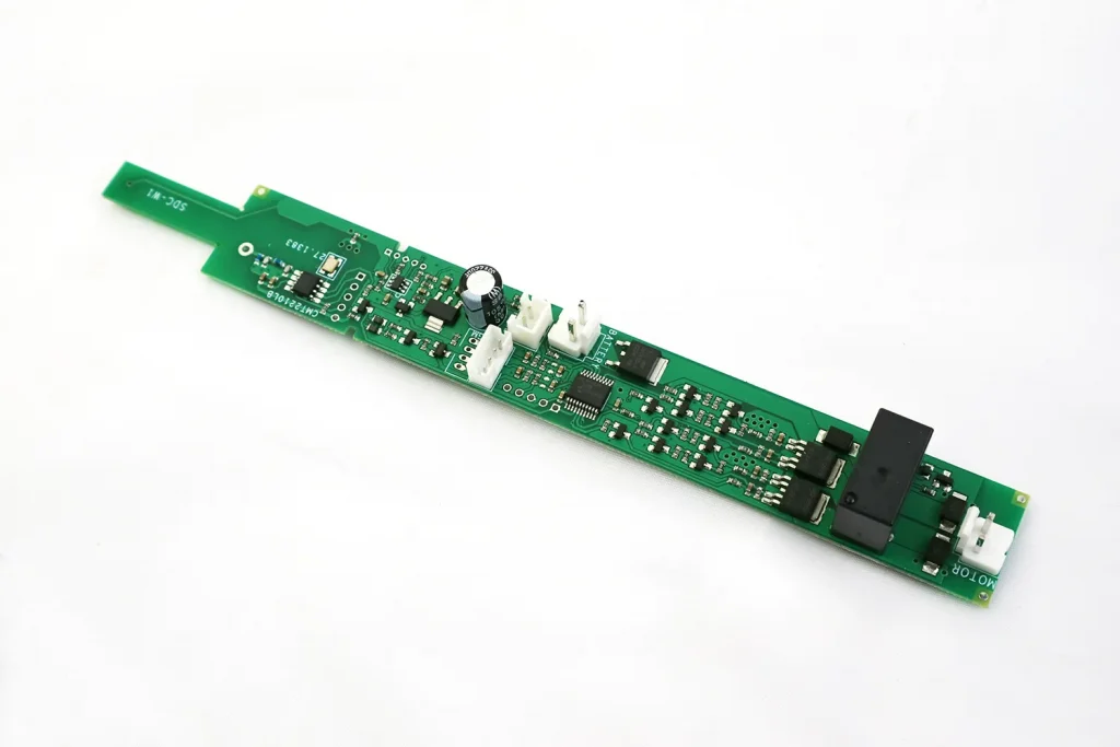
Mechanical vs Electronic Limit Switch
Neither system is universally better. The correct choice depends on the application, control architecture, installer capability, access for future adjustment and after-sales requirements.
| Comparison | Mechanical limit | Electronic limit |
|---|---|---|
| Setting method | Physical adjustment of cams through screws or a model-specific tool. | Stop positions saved through an electronic programming sequence. |
| Adjustment convenience | Direct and familiar where the motor head remains accessible. | Can support control-based setup, depending on the model and controller. |
| Control integration | Common in straightforward wired systems; external controls may still be added. | Often selected where receiver or smart-control functions are part of the confirmed motor system. |
| Power-loss behavior | Mechanical cam positions normally remain physically set. | Saved-position behavior depends on the electronics and model design; confirm it before selection. |
| Typical applications | Standard shutters, blinds, awnings and screens with accessible commissioning. | Projects requiring electronic commissioning or integration with compatible controls. |
| Commissioning requirements | Correct screw identification, installation direction and careful incremental adjustment. | Correct programming sequence, compatible control device and confirmation of both endpoints. |
| Maintenance considerations | Inspect mechanical adjustment, crown engagement and physical wear if position changes. | Check power, saved settings, controller compatibility and electronics before replacing parts. |
Upper and Lower Limits Explained
Upper limit
For a roller shutter, the upper limit stops the curtain at its fully open position without forcing the slats or stops. For a roller blind, it prevents excessive fabric from winding onto the tube.
Lower limit
The lower limit stops the shutter bottom bar, blind fabric, awning or screen at the intended extended position without continued drive against the end point.
What Happens When Limits Are Set Incorrectly?
Stops too early
The usable opening or drop is reduced because an endpoint is stored or adjusted too short, or because another protection condition is active.
Continues at the end
The limit may be unset, adjusted in the wrong direction, not engaged correctly or affected by a component fault. Stop testing before damage occurs.
Fabric or bar inconsistency
Loose fabric, over-tension, changing bottom-bar position or uneven travel can indicate a limit, tube, accessory, load or installation problem.
Protection activates
Repeated forcing, overload or extended running may activate motor protection. Allow safe inspection instead of repeatedly restarting the motor.
Repeated mechanical stress
Driving against an endpoint can stress fabric, slats, brackets, crowns, drives, the motor and the supporting structure.
Position is lost
For an electronic system, investigate saved settings, supply, control compatibility and the model-specific feedback path.
Model-Specific Limit Setting Guidance
- Commission the motor with the application able to move safely and stop testing if travel becomes blocked.
- Set and verify both endpoints in small, controlled steps.
- Confirm the curtain, fabric or screen is correctly attached and the tube, crown and drive are engaged.
- Run a complete up-and-down check after adjustment and observe load, stopping and direction.
- Use the product manual or request technical support when the setting symbols or programming sequence are uncertain.
Common Limit Setting Problems and Causes
| Symptom | Likely cause | Safe check | Contact technical support when |
|---|---|---|---|
| Motor stops before the end position | Endpoint set too short, obstruction, load issue or protection state. | Stop movement, inspect the travel path and compare with the model instructions. | The motor still stops early after safe load and setting checks. |
| Motor does not stop at an endpoint | Limit not set, wrong adjustment direction, mechanism not engaged or component fault. | Stop operation immediately; do not continue forcing the application. | The correct model procedure does not restore controlled stopping. |
| Up and down behavior is reversed | Direction or wiring/control configuration does not match the installation. | Verify the product wiring and direction procedure before setting endpoints. | Direction cannot be corrected using the applicable documentation. |
| Mechanical adjustment has no effect | Wrong screw, wrong direction, crown not tracking tube movement or internal fault. | Confirm model, adjustment symbol, installation orientation and crown engagement. | Adjustment remains ineffective or the mechanism appears damaged. |
| Electronic limit loses or rejects a setting | Incorrect sequence, incompatible control, power interruption or electronic fault. | Verify the exact programming sequence, power supply and paired control. | The model repeatedly fails to save or retain both endpoints. |
| Motor protection activates repeatedly | Overload, obstruction, excessive running or forced end position. | Stop cycling, allow safe cooling where applicable and inspect load and travel. | The cause is not clear or protection repeats under normal conditions. |
Applications
Roller blinds
Limit control determines the top wrap and the finished fabric drop. Tube diameter, crown engagement and fabric attachment affect the result.
Roller shutters
Both endpoints must protect the curtain, slats, bottom bar and shutter stops while operating under the specified load.
Awnings
Extension and retraction limits must suit the awning mechanics, fabric tension and approved motor configuration.
Zip screens
Correct stop positions support screen tension and prevent unnecessary force at the top or bottom of travel.
Projection screens
The lower endpoint establishes the viewing position while the upper endpoint controls safe retraction into the housing.
How B2B Buyers Should Choose a Limit System
OEM buyers, distributors and system integrators should specify the limit system together with the complete motor and application rather than treating it as an isolated feature.
Application and access
Define the blind, shutter, awning or screen, expected load, installation orientation and whether the motor head remains accessible after installation.
Control method
Confirm wired switching, receiver, transmitter, building control or smart integration and the exact compatibility requirements.
Commissioning capability
Match the setting method to installer skills, available tools, documentation language and expected adjustment frequency.
After-sales support
Consider how settings will be checked, reset or diagnosed after installation and what product identification is available.
Accessory compatibility
Confirm tube diameter, crown, drive wheel, bracket, controller and other accessories as one system.
Order documentation
Include motor model, voltage, torque, speed, limit type, control method, application and required accessories in the RFQ.
Walter Motor Quality-Control Perspective
Walter’s published quality-control process includes limit-system assembly checkpoints, direction and functional checks, limit setting and repeatability checks, travel validation, load-related testing where applicable, assembly inspection and electrical-safety checks according to the motor type and order requirements. These checks are not a promise that every motor uses one identical test plan; the inspection scope must match the confirmed product and project.
Assembly inspection
Limit-system parts, motor assembly and accessory fit are reviewed as applicable to the selected product.
Functional verification
Direction, stopping behavior, travel and control response can be checked according to motor type.
Electrical and load checks
Electrical-safety and load-related validation are applied where required by the product and agreed inspection plan.
Related Motors and Technical Guides
Tubular Motor Core Guide
Definition, structure, working principle and related technical topics.
Tubular Motor Products
Review Walter motor families before requesting model selection.
Selection Guide
Match tube, load, torque, control and application requirements.
Installation
Review system installation and commissioning considerations.
Troubleshooting
Check common motor, control and application symptoms safely.
Roller Shutter Limit Setting
Application-specific limit setting guidance for roller shutters.
Frequently Asked Questions
What is a limit switch in a tubular motor?
It is the system that defines the upper and lower stop positions of the motor so a blind, shutter, awning or screen stops at the required endpoints.
How does a mechanical tubular motor limit switch work?
A geared counting mechanism normally moves adjustable cams as the motor or tube turns. At a preset position, the relevant cam operates the stop mechanism or interrupts that direction’s circuit.
What is the difference between mechanical and electronic limits?
Mechanical limits use physically adjusted cams. Electronic limits save stop positions through electronic control logic and a model-specific feedback method. Neither type is universally better for every project.
Why does a tubular motor stop before the end position?
The limit may be set too short, or the system may have an obstruction, load issue, control problem or active motor protection. Stop and check the application before changing settings.
Can one limit-setting method be used for every motor?
No. The correct process depends on the motor model, installation direction, rotation direction, limit type and control interface. Use the applicable product instructions.
What happens if the upper or lower limit is set incorrectly?
The application may stop too early, over-travel, over-tension fabric, force shutter parts, change the bottom-bar position or repeatedly activate motor protection.
Do electronic-limit motors require a remote control?
Not always. Some models use a transmitter, receiver sequence, wall control or programming tool. The required setting interface depends on the confirmed motor and controller.
How should OEM buyers choose a limit system?
Specify the application, motor access, control method, installer capability, adjustment frequency, after-sales requirements and compatibility with the tube, crown, drive, brackets and controls.
Need a Limit System for an OEM or Project Application?
Send Walter Motor the application type, tube size, load information, required control method, installation conditions and expected accessories. The team can help narrow the suitable tubular motor and limit-system options for your RFQ.

