
Buyer Question
Roller Shutter Limit Setting Guide for Motor Buyers and Installers
Limit setting is not only an installer adjustment. For OEM buyers, distributors and project teams, it affects motor protection, shutter travel, commissioning time and after-sales support before installation and before shipment.
The buyer decision
Roller shutter limit setting defines the upper and lower stop positions of the shutter. If the limits are wrong, the shutter may stop too early, overrun the end position, push against the box, strain the slats or keep loading the tubular motor after the curtain has reached its travel end.
For a single installation, this is a commissioning issue. For a batch order, it becomes a documentation and support issue. Buyers should confirm how the selected motor is adjusted, what documents installers will receive and whether the limit system matches the control method specified in the RFQ.
Buyer takeaway
Confirm the limit-setting method before comparing quotations.
A good roller shutter motor quotation should include the limit-setting method, installer document, control compatibility and commissioning support, not only torque, speed and price.
What is roller shutter limit setting?
Roller shutter limit setting is the process of defining where a tubular motor stops when the shutter is fully open and fully closed. The upper limit protects the shutter from being pulled too far into the headbox. The lower limit controls the closed position so the curtain reaches the bottom without excessive force.
For professional buyers, limit setting should be confirmed before shipment because the setting method affects installation documents, accessory compatibility, control selection, after-sales support and the final commissioning checklist.
Why limit setting is critical
| Buyer concern. | Why limit setting matters. |
|---|---|
| Motor protection. | Correct stop positions prevent the motor from continuing to load gears, brakes and bearings after the shutter reaches its travel end. |
| Shutter longevity. | Proper limits reduce slat deformation, end-stop damage, shaft stress and guide rail strain. |
| Smooth operation and noise control. | Repeatable stop positions reduce hard impact, scraping noise and unnecessary vibration during daily use. |
| Safety and compliance review. | Limit setting helps prevent uncontrolled overrun and supports safer commissioning with certified motors and components. |
Limit system types buyers should separate
| Limit system | Typical setting method | Buyer should confirm |
|---|---|---|
| Mechanical limit switch. | Adjustment screws or a setting rod on the motor head. | Which screw controls each direction, adjustment direction, required tool, and installer instruction sheet. |
| Electronic limit motor. | Remote control, wall switch, or controller programming sequence. | Programming steps, reset method, remote model, receiver type, and whether the procedure is locked after commissioning. |
| Smart or encoder-based system. | Digital position learning, app, controller, or self-learning sequence depending on model. | Supported control ecosystem, power requirements, fault reset process, and field-service guidance. |
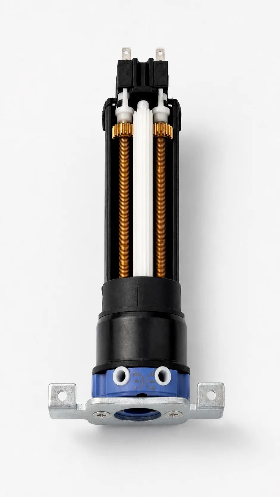
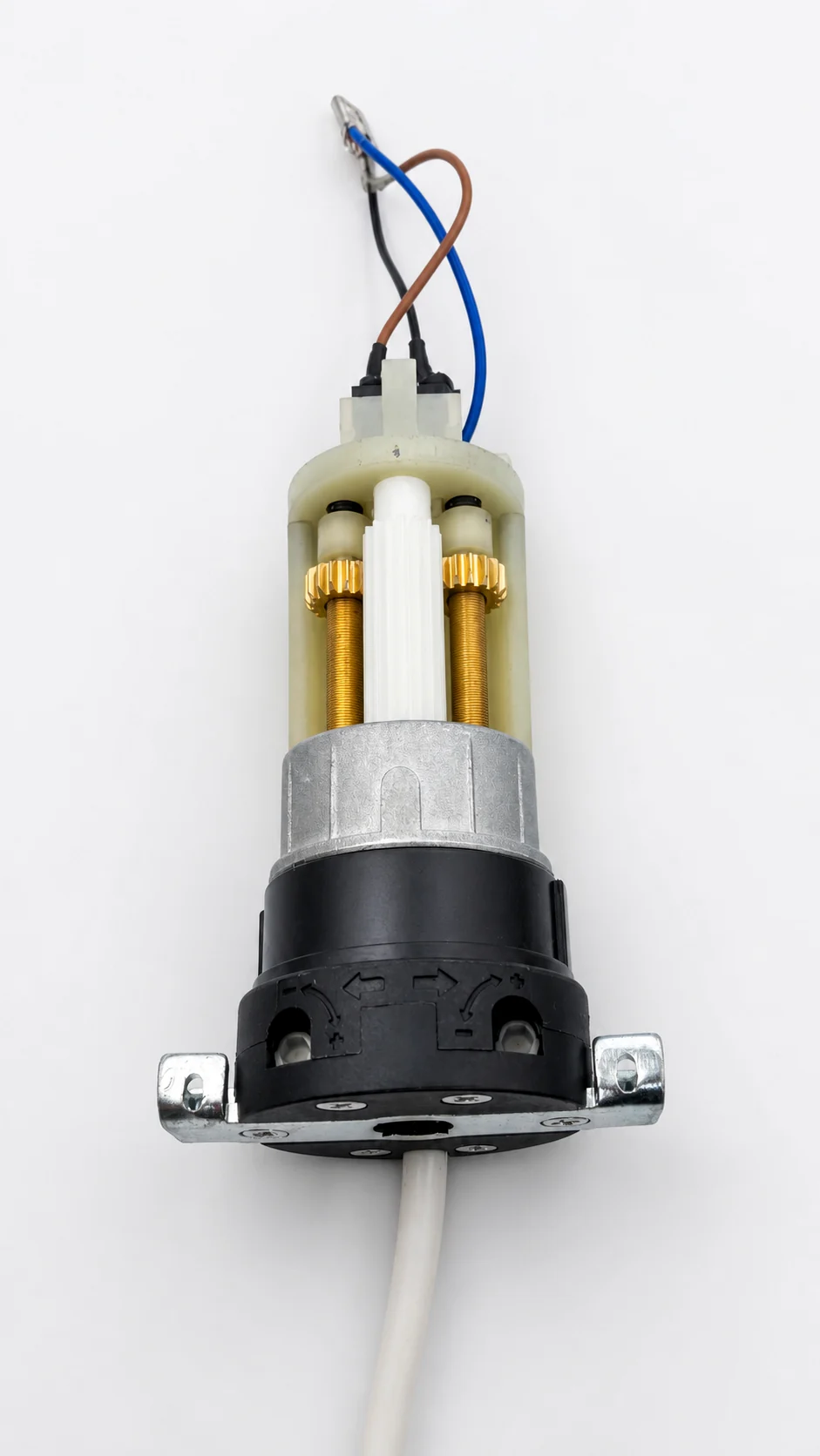
Mechanical limit switch examples for 35mm and 45mm motors
These examples show mechanical limit switch assemblies used in compact 35mm and standard 45mm tubular motors. The adjustment principle is similar, but the motor head, screw position, wiring, and installer instruction should be confirmed by exact model.
Application examples where limit setting matters
The same confirmation logic applies beyond one roller shutter project. Roller shutters need stable end positions for security and guide rail alignment. Roller blinds need quiet, repeatable stopping for fabric protection. Garage doors and heavier shutter systems need careful torque and safety checks. Awnings and zip screens also depend on correct travel control to protect fabric, tubes, brackets and control systems.
Basic mechanical limit setting logic
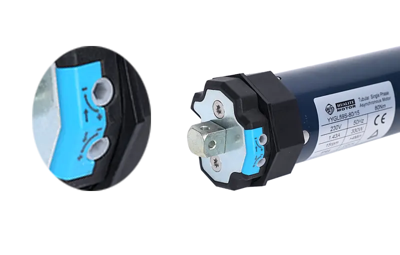
Most mechanical tubular motors use two limit circuits inside the motor head. One circuit stops the motor in the opening direction, and the other stops the motor in the closing direction. The adjustment screws do not change motor torque. They only change the stopping position by allowing more or less travel before the internal limit switch cuts power to that direction.
Because the motor can be installed on the left or right side of the shutter tube, the same screw symbol may not always feel intuitive to the installer. The correct method is to follow the symbols on the actual limit head, adjust in small increments, and test movement after each change.
Mechanical lower limit setting steps
Mechanical limit motors remain common for roller shutter projects because the structure is simple and reliable. The adjustment should be done after the shutter tube, brackets, guide rails, crown and drive wheel are installed.
- Run the shutter downward until it is close to the intended closed position.
- Stop before the slats press hard against the sill, guide rail end, or bottom stop.
- Adjust the lower limit screw in a small increment according to the motor head symbol.
- Run the shutter down again and check whether the stop point moved in the expected direction.
- Repeat with small adjustments until the shutter closes fully without excessive pressure.
- Record the adjustment direction for the installer or after-sales team when the project requires documentation.
The lower limit should create a firm closed position, not a forced compression point. Excessive closing travel can deform slats, stress the end stops, or make the motor appear overloaded even when the motor itself is correctly selected.
Mechanical upper limit setting steps
- Run the shutter upward and stop before it enters the headbox too tightly.
- Adjust the upper limit screw in a small increment according to the symbol on the motor head.
- Test upward movement again and watch the final stopping position.
- Keep enough clearance so the curtain, shaft, and end stops do not strike the box or support structure.
- Check that the shutter remains aligned in both guide rails at the upper stopping position.
- Confirm the open position is repeatable before handing the unit over to the installer or customer.
For buyers, the key point is documentation. A supplier should provide model-specific limit instructions instead of sending generic advice that does not match the motor head, control method, or accessory set.
Electronic limit setting logic
Electronic limit motors store the upper and lower travel positions through the motor control logic instead of a visible mechanical screw. Depending on the model, the installer may use a remote handset, wall switch sequence, receiver button, controller, or app-supported learning process.
The basic logic is similar across many systems: enter setting mode, move the shutter to the upper position, save it, move the shutter to the lower position, save it, then exit setting mode and test repeatability. The exact sequence must come from the selected motor documentation because an incorrect reset or programming command can erase existing limits.
- Confirm the sequence for entering and exiting limit-setting mode.
- Confirm how the upper and lower positions are saved.
- Confirm whether a power-cycle reset will erase existing limits.
- Confirm whether the remote, wall switch, receiver or app is required during commissioning.
- Keep a troubleshooting note for wrong direction, lost remote pairing and early stopping.
Final 3-cycle testing checklist
After the upper and lower positions are set, run at least three complete open-close cycles. The test should be slow and deliberate enough to catch noise, resistance, and stop-position drift before the shutter is handed over.
| Check. | What to verify. | Why it matters. |
|---|---|---|
| Three full cycles. | Run at least three complete open-close cycles without changing the limit screws between cycles. | Confirms the setting is not a one-time stop caused by friction, heat, or inconsistent travel. |
| Repeatability. | The shutter stops at the same upper and lower positions on each cycle. | Shows the limit system, tube, crown, drive wheel, and curtain movement are stable. |
| Noise. | Listen for scraping, knocking, hard end impact, or sudden change in motor sound. | Helps separate limit-setting errors from shutter alignment or accessory-fit problems. |
| Guide rail resistance. | Watch whether the curtain binds, tilts, or slows down in the guide rails. | High resistance can make a correct motor and correct limit setting appear faulty. |
| Thermal protection. | Respect the motor duty cycle and allow cooling time if the motor stops after repeated testing. | Prevents a normal thermal-protection pause from being misdiagnosed as a limit switch failure. |
Safety notes before adjustment
- Disconnect power before inspection: isolate power before opening the headbox, checking wiring, touching the motor head, or inspecting mechanical parts.
- Keep hands clear during testing: do not place hands near the tube, guide rails, slats, end stops, or moving curtain while the motor is powered.
- Never force the shutter manually: forcing the curtain against motor resistance can damage gears, brakes, brackets, slats, or the limit mechanism.
- Use qualified installers: wiring and commissioning should follow the selected motor instructions and local electrical safety rules.
Common limit setting problems and solutions
| Symptom. | Likely causes. | What to check first. |
|---|---|---|
| Shutter stops too early. | Limit travel is set too short, guide rails have resistance, the curtain is misaligned, or electronic limits were saved before the correct position. | Check guide rail resistance, then adjust the relevant limit in small increments and retest. |
| Motor does not stop at the end position. | Limit direction was adjusted the wrong way, the wrong screw was turned, the microswitch is damaged, or the controller sequence is incorrect. | Stop testing immediately, verify the limit head symbols, and inspect the selected motor instructions. |
| Shutter overruns into the box or bottom stop. | The upper or lower limit is set too far, end stops are missing, or the shutter is being forced against the structure. | Reduce travel distance, check end stops, and confirm the curtain is not pulled too tightly. |
| Motor pauses after repeated operation. | The motor may be in thermal protection after too many test cycles, especially during commissioning. | Allow the motor to cool down, then retest within the stated duty cycle. |
| Stop position changes after installation. | Tube alignment, crown fit, drive wheel fit, bracket position, or shutter resistance may have changed under load. | Check accessory compatibility and installation alignment before assuming the motor limit system is faulty. |
| Abnormal scraping or knocking noise. | Guide rail friction, slat deformation, hard end impact, or a shutter box clearance problem may be present. | Inspect mechanical movement and adjust the stopping point before continuing repeated cycles. |
Factory best practices for buyers
From a factory perspective, limit setting should be treated as part of the product support package. The motor can pass a factory running test and still require final travel adjustment after the shutter, tube, brackets, crown, drive wheel and guide rails are installed on site.
- Set limits after installation: do not rely on factory default travel positions because shutter size, tube diameter, bracket position and guide rail resistance vary by project.
- Adjust in small increments: large screw adjustments increase the risk of overshooting the correct stop point and damaging the shutter.
- Match torque before adjustment: poor torque selection can make limit setting unstable, especially when the shutter is heavy or guide rail friction is high.
- Record final settings: keep the limit direction, control method and final commissioning notes for maintenance and after-sales support.
- Train installers with model-specific documents: many field problems are installation or setting issues, not motor defects.
RFQ checklist for limit setting support
Before confirming samples or batch production, send the motor supplier enough project information to prepare the right limit-setting guidance.
- Motor voltage, torque, tube diameter and control type.
- Mechanical limit, electronic limit or smart control requirement.
- Wall switch, RF remote, receiver, dry contact or smart gateway details.
- Market language required for installer documents.
- Whether OEM branding is needed on manuals or labels.
- Photos or drawings of shutter tube, bracket, guide rail and headbox conditions if available.
Documentation to request
Ask for the documents that installers and after-sales teams will actually use during commissioning.
- Limit-setting instruction
- Wiring diagram
- Remote or switch procedure
- Accessory assembly drawing
FAQ
What is roller shutter limit setting?
Roller shutter limit setting defines the upper and lower stop positions of a tubular motor so the shutter opens and closes to the correct travel points without overrun or excessive pressure.
What is the upper limit of a roller shutter motor?
The upper limit is the open stopping position. It prevents the shutter curtain from being pulled too tightly into the headbox or hitting the tube, box, shaft or end-stop structure.
What is the lower limit of a roller shutter motor?
The lower limit is the closed stopping position. It allows the shutter to close fully while avoiding unnecessary force on the sill, bottom stop, slats or guide rails.
How do you set a mechanical roller shutter motor limit?
Use the limit screws or setting rod on the motor head, follow the direction symbols on the exact motor model, adjust in small increments, and test the shutter after each adjustment.
Why can a shutter stop early even when the motor is not defective?
Early stopping can come from conservative limit settings, guide rail resistance, curtain misalignment, thermal protection, or an electronic limit saved before the final travel position.
Why does a tubular motor not stop at the end position?
The likely causes include wrong screw direction, incorrect limit adjustment, damaged microswitch, controller logic error, electronic limit miscalibration, or an installation problem that prevents normal travel.
Should limit setting be confirmed before shipment?
Yes. Buyers should confirm the limit system type, adjustment method, installation document, control method and troubleshooting support before sample approval or batch shipment.
What information should buyers send before asking Walter Motor for a recommendation?
Send the application, shutter size and weight, tube diameter, voltage, torque expectation, control method, market requirements, accessory details and any OEM documentation needs.
Walter Motor support position
Walter Motor supplies tubular motors for roller shutter applications and can provide model-specific wiring diagrams, limit-setting instructions and accessory confirmation for OEM and project buyers. The correct document depends on the selected motor series, control option and market requirement, so final instructions should be confirmed against the exact model before shipment.
Best next step

Share project voltage, tube size, shutter weight, control method and market so the correct motor and limit-setting document can be matched.
Request limit-setting supportPrepare a cleaner roller shutter motor RFQ.
Send the expected control method, tube and accessory details, market requirements and installation document needs before sample confirmation.